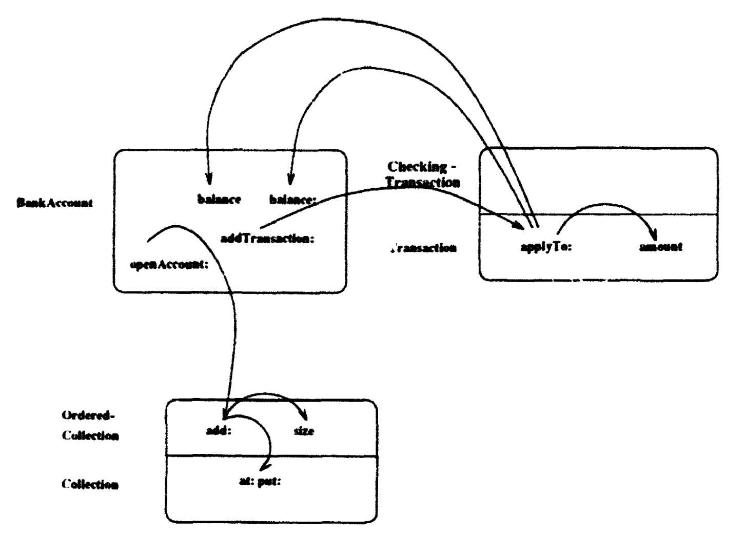
Cunningham and Beck introduced a notation for diagraming the message sending dialogue that takes place between objects participating in an object-oriented computation [CB 86]. Here, an object-oriented computation is the same concept as the use case which we described in the previous chapter.
They represent an object as a box and draw a message send as a directed arc landing within the receiving object. When one object invokes a computation in another object through a message send, the message send is shown as an arc originating from the sending object and landing in the receiving object. The selector of methods invoked by messages are placed at the receiving end of a message arc. An object is identified by its class. Class names are shown beside the objects' box. When a method is inherited from another class, the receiver will be divided into layers to represent the classes involved. It will show the class of the receiver, its superclass, superclass' superclass (if applicable) until the class which implements the method is found. The method selector will be placed in the layer which implements the method. Deeper layers will be superclasses. The top layer will be that of the object's own class. A message arc goes from top layer through several layers until it finds its selector in a deeper layer.
Cunningham diagrams were implemented by extending Smalllalk-80’s debugger. They added an additional pane on the right as a diagram editor. Information is added to the diagram by execute debugger's commands *step* and *send* which duplicate the ordinary debugger commands and record the message in the diagram.
Figure 3.1 shows a Cunningham diagram. The computation of the diagram is to open a bank account and make a checking transaction in a simple bank account application. The sample Smalltalk code is shown in Appendix A.

Figure 3.1: Cunningham Diagram
We can see from figure 3.1 that Cunningham diagrams could become complex and difficult to follow when a system becomes large and complicated. The diagram does not represent the sequence of computation. Although we can see the objects involved in a computation and message sends between these objects, the order of the computation is not easy to follow. In addition, the diagram's layout may be cumbersome for describing large systems.
Cunningham diagrams are early attempts to help people understand object-oriented systems. The authors have used these diagrams to teach beginning and advanced object-oriented programming to more than one hundred students. It influenced on our Interaction Diagram Generator in that we also adopted the approach of reusing Debugger class in Smalltalk.
~
WANG, Yun, 1994. Interaction diagram generator. A tool for visualizing use cases in Smalltalk. PhD Thesis. Carleton University. pdf ![]()
I (Ward) developed a notation that organized a subroutine call graph over regions representing object instances. Called routines were shown in strata corresponding to the inheritance in play for the particular instance.