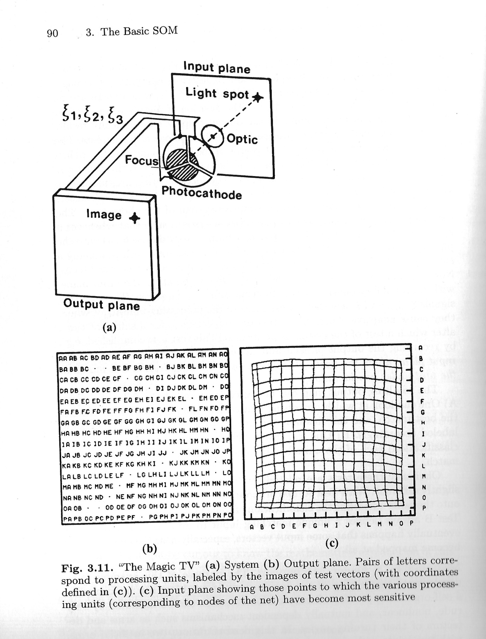
“The Magic TV”. The following demonstration, Fig. 3.11 shows another, more concrete example of Self-Organization.
~
Fig. 3.11. “The Magic TV” (a) System (b) Output Plane. Pairs of letters correspond to processing units, labeled by the images of test vectors (with Coordinates defined in (c)). (c) Input Plane showing those points to which the various processing units (corresponding to nodes of the net) have become most sensitive

~
It describes a hypothetical image-transferring system (dubbed here “The Magic TV”) in which there are no control mechanisms for the encoding of the position of picture elements, but where the order of image points in the output display automatically results in the self-organizing learning process from their topological constraints.
The result is a one-to-one mapping of the points of the input plane onto the points in the output plane; in the transmission of the signals, however, this order was never specified explicitly. The system has to deduce the order gradually from the relations that are implicit in the transmitted signals. This system consists of a primitive “TV camera” and an adaptive system of the above type. The camera is thought to have a very poor optical system, such that whenever a spot of light appears on the input plane, it forms a very diffuse focus onto the photocathode.
Assume that the cathode has three sectors, each producing a signal directly proportional to the area that is illuminated by the broad focus. Now let the light spot move at random in different points in the input plane, with a probability density that is uniform over a square area. The resulting signals 𝜉_1, 𝜉_2, and 𝜉_3 are then transmitted to the processing-unit array, where they cause adaptive changes.
Let this process continue for a sufficient time, after which a test of the system is performed. This test is accomplished, e.g., by recording the output of each unit in turn and locating that point in the input plane where the light spot must be in order to cause the best match in the unit under consideration.
The resulting output map can be tested in either of the following ways: A) One can look at which processing unit each of the test vectors in turn has the best match, and call this unit the image of the test vector. The array is labeled accordingly. B) One can test to which training vector (with known classification) each of the units has become most sensitive, making the best match.
Obviously these tests are related, but the respective output maps look slightly different. With Test A, two or more test vectors may become mapped onto the same unit while the classification of some units may be left undefined. Test B always defines a unique matching input to every output unit but it eventually happens that some input vectors, especially near the edges, do not become mapped at all.
~
KOHONEN, Teuvo, 1995. Self-organizing maps. Berlin ; New York: Springer. Springer series in information sciences, 30. ISBN 978-3-540-58600-5, p. 90
⇒ Bit-Boundary Block Transfer: The Wheel