Numerous stereometric optical techniques and moire methods for topographic applications have been devised; these often require complex transformations for data reduction.
We describe an alternate approach in which a laser-generated rectangular light grid pattern is projected on the object, revealing the surface topography very much as a computer-generated 3-D plot. The generation of a rectangular fringe pattern for topographical applications is obtained through the interference of front and back reflections from a coated thin glass plate.
It is interesting to note that similar fringes have recently been observed in the reflections of a laser beam from a corneal surface. The condition for optimum interference fringe formation is derived, and a specific embodiment of an instrument for rectangular grid generation is presented.
~
TABOADA, J. and ALTSCHULER, B. R., 1976. Rectangular grid fringe pattern for topographic applications. Applied Optics. 1 March 1976. Vol. 15, no. 3, p. 597–599. DOI 10.1364/AO.15.000597.
[…]
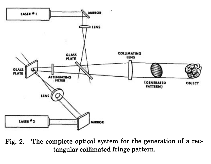
Using the principle of fringe generation as outlined above, a schematic of the apparatus to generate a rectangular grid is shown in Fig. 2. The complete optical system for the generation of a rectangular collimated fringe pattern.

Two lasers are used to generate separate orthogonal fringe patterns. The glass plates are standard 1 mm thick, Inconel 0.2 o.d. filters, positioned with the metal surface away from the diverging beam and at an angle of about 60° to the main optical axis running through the collimating lens. The diverging lenses have focal lengths of 48 mm. Laser 1 is a Spectra-Physics model 155 1-mW He-Ne laser, and laser 2 is a Spectra-Physics model 132, 3-mW He-Ne laser. The fringe pattern generated by laser 2 is projected orthogonally through the fringe generating plate of laser 1. The collimating lens has a focal length of about 65 cm. An attenuating filter of the appropriate density was introduced in the path of laser 2 to compensate its greater intensity.
The visibility of the fringe grid pattern, when projected on an object, is greatest for matte reflecting surfaces; […] The topographic information is clearly coded into the distortions of the grid pattern as it is projected on these surfaces. Numerical metrological values can be conveniently retrieved by projecting a calibrated orthogonal set of axes (deduced from the relative angles of the grid pattern and camera axis) onto a photograph of the object and pattern. In principle, since the fringe spatial frequency can be increased with beam-contracting optics, studies of objects ranging to microscopic size can be performed; the only limitation may be the coherent modulation transfer function of the optical components.
~
⇒ Light Spot ⇒ Optic ⇒ Photocathode ⇒ Focus ⇒ Image
DOT FROM lambda-browsing